Our Services and Products
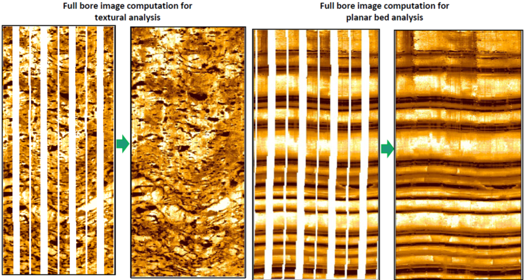
IMAGE PROCESSING
Supporting all wireline imaging tools, in vertical and lateral wells, including EMI, FMI, OBMI, FMS, Earth Imager, XRMI, UBI, CBIL, STAR, RAB, OBMI, Dual-OBMI ThruBit and Quanta Geo

INTERPRETATION SERVICES
Focused mostly on bedding, sedimentary dips, textural and porosity analysis in Carbonates, faults, natural fractures and stress.
BOREHOLE IMAGE
PROCESSING AND QC
FULL IMAGE
COMPUTATION
IMAGE
CALIBRATION
INTERACTIVE DIP PICKING OF
GEOLOGICAL FEATURES
STRUCTURAL
ANALYSIS
SEDIMENTARY
ANALYSIS
FACIES
ANALYSIS
Borehole Image processing and QC
Imaging Services Applied to:
• FMS, FMI, FMI-HD (SLB)
• OBMI, Dual OBMI (SLB)
• UBI (SLB)
• Quanta Geo (SLB)
• CBIL, Earth Image (Baker)
• EMI, CAST, OMRI (Halliburton)
Deliverables:
• QC Report
• 1:20 & 1:240 scale processed image log prints (PDF)
• Enhanced (processed) image log data in DLIS & XML
Benefits:
• Processed images are improvement on “raw” acquisition images, and provide clearer feature recognition.
• Quick-turnaround enhanced quality images for operational decisions, such as MDT and MSCT.
• QC report provides quick image quality review & provides recommendations for further interpretation based solutions.
Turnaround time (TAT):
• Standard TAT is 1-2 days (determined by image log length & image quality).
• Rush TAT arranged prior to operations can be completed in 24 hrs. after acquisition.
Primarily, computer processing of borehole image data is to convert the raw acquisition data into the best visual representation. The primary software to be used is Techlog developed by Schlumberger, which will support all imaging tools from main service companies, both wireline (WL) and logging while drilling (LWD).
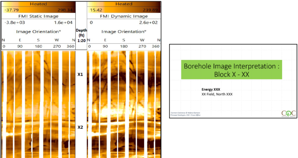
Pre-processing is carried out in line with standard processing of borehole images. It includes several steps that can be summarized as follows. Resistivity measurements are first accurately positioned in depth using accelerometer measurements, button sensor responses are then harmonized to have similar gain and offset, for the last step of the pre-processing, called pad concatenation, the method computes the image geometry from accelerometer and magnetometer data and combines the different pad measurements into one single 2D calibrated image. Following this step, standard color mapping is applied to the 2D image, with the light and dark color palette corresponding to the calibrated resistivity range. Low and light color represents the most resistive response and high and dark color for the most conductive response. Compared to the raw image, these images are significantly improved quality, and can be used for detailed interpretation. Images can be processed in rush time if required to provide input to further operations such as pressure, sampling and sidewall coring point selection.
Full Image Computation
Imaging Services Applied to:
- FMS, FMI, FMI-HD
- Quanta Geo
- (Best results when BS ≤ 8.5in)
Deliverables:
- 1:20 & 1:240 scale standard processed & full image computed image log prints (PDF).
- Full Image computed image data (DLIS & XML).
Benefits:
- Full image provides better input for Matrix computation, textural and fracture analysis.
- Improved visualization of geological features, such as texture, fractures & bedding.
Turnaround time (TAT):
- Standard TAT is 1-2 days (determined by image log length & image quality).
Full Image Computation
Is a Techlog plug-in that automatically fills the empty zones of a borehole image. Most wireline imaging tools acquire data from pads / flaps on mechanical arms and therefore feature strips of missing information. This display by strips does not affect greatly the bed boundary picking but significantly complicates the delineation of texture and fractures especially for automated processing.
Full Image Computation for Techlog was developed for the purpose of filling gaps in images. It is a useful tool to reproduce complex textures with various orientations, such as vugs and fractures in carbonates. The result is a reasonable full-bore image with 360 deg of coverage
Full Image uses an algorithm from multi-point geostatistics (FILTERSIM), combined when needed with another algorithm (Inpainting). The combination of Inpainting with FILTERSIM leads to a robust and universal approach for full-bore reconstruction, regardless of the depositional environment. Results can then be used for more accurate automated textural and fracture analysis, and provide generally improved visualisation of many geological features (e.g. bedding, vugs, etc.)

Image Calibration
Imaging Services Applied to:
- FMS, FMI, FMI-HD (Image Calibration)
Deliverables:
- Resistivity calibrated FMI image (DLIS, XML) and high resolution resistivity curves (LAS, DLIS, XML)
Benefits:
- Calibrated FMI image can be used in various advanced interpretation products requiring a calibrated electrical image.
- High (0.2in vertical) resolution resistivity channel for comparison with other resistivity tools.
Turnaround time (TAT):
- Standard TAT is 1 days.
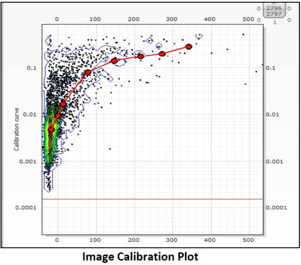
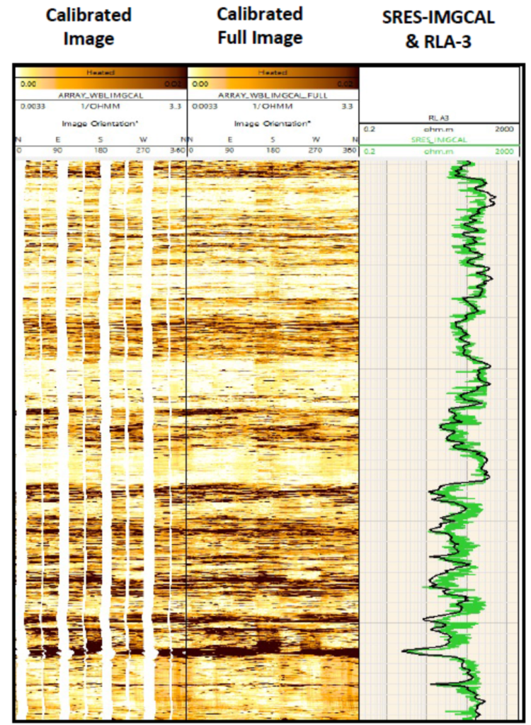
Image Calibration
Image calibration consists in scaling the image into conductivity units using an external shallow resistivity log variable from another resistivity measuring tool. The method calculates automatically a best guess calibration using a series of linear regressions.
It produces a calibrated FMI image and extracts a single high resolution (0.2in vertical) resistivity channel (SRES), which can be used for direct comparison with other resistivity tools.
The main application of Image calibration is for advanced processing products which require a calibrated electrical image, such as and between others: Matrix Computation, Fracture Aperture analysis and Lamination Analysis. It produces a calibrated FMI image and extracts a single high resolution (0.2in vertical) resistivity channel (SRES), which can be used for direct comparison with other resistivity tools.
Interactive Dip Picking of Geological Features
Imaging Services Applied to:
- FMS, FMI, FMI-HD (SLB)
- OBMI, Dual OBMI (SLB)
- UBI (SLB), Quanta Geo (SLB)
- CBIL, Earth Image (Baker)
- EMI, CAST, OMRI (Halliburton)
Deliverables:
- Image Interpretation Summary Report in Power point format.
- 1:20 & 1:240 scale processed image & dip picking interpretation log prints (PDF).
- Dip sets in LAS, XLS , XML
Benefits:
- Identification and true dip orientation of all planar features visible on image log:
- Structural bedding,
- Sedimentary bedding
- Faults & Fractures.
- Identification and true dip orientation of geomechanical features:
- Borehole breakout,
- Drilling induced fractures.
- Interpretation report providing summary statistics for all features identified.
Turnaround time (TAT):
- Standard TAT is 5-7 days (determined by image log length & image quality).
- Rush TAT with focus on specific features (e.g. stress orientation and fault identification) can be achieved in 24hrs after acquisition.
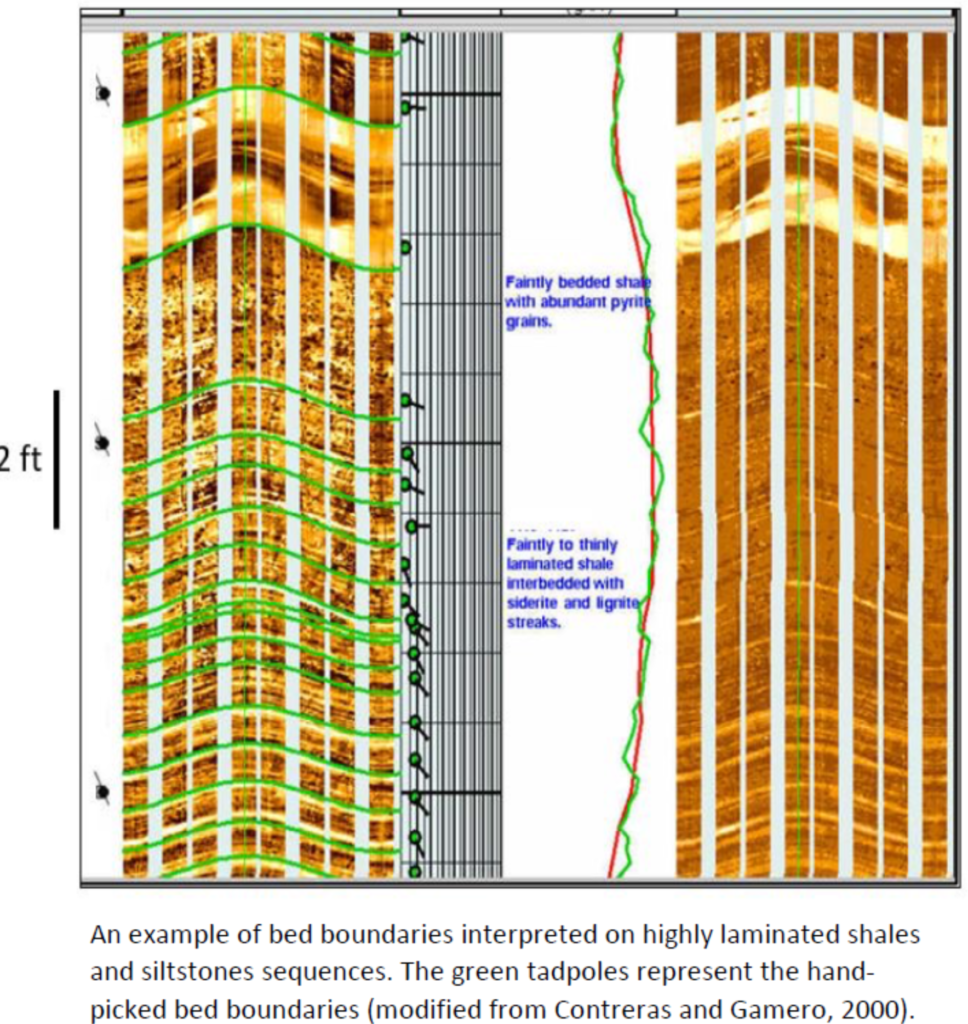
This is the first stage of image interpretation, and enables the identification, classification, and true dip orientation, of bedding planes, fractures, faults, drilling induced fractures, breakouts or any planar feature visible on the image log. This is achieved in Techlog software by placing sinusoids over planar features on the unwrapped oriented borehole image, with the true dip of these features automatically calculated and displayed as tadpoles. The orientation of geomechanical features for stress orientation is determined using breakout and induced fracture dip picking modes. The dip picking results can be used as inputs for more detailed structural, sedimentary or geomechanical interpretation workflows.
Along with a processed image & dip picking interpretation log print, a summary report in power point format is provided which summarises statistics for all features identified on the image log.

Structural Analysis
Imaging Services Applied to:
- FMS, FMI, FMI-HD (SLB)
- OBMI, Dual OBMI (SLB)
- UBI (SLB), Quanta Geo (SLB)
- CBIL, Earth Image (Baker)
- EMI, CAST, OMRI (Halliburton)
Deliverables:
- Image Interpretation Summary Report in Power point format.
- 1:20 & 1:240 scale processed image & dip picking interpretation log prints (PDF).
- Dip sets in LAS, XLS, XML
Benefits:
- Identification and true dip orientation of all planar features visible on image log:
- Structural bedding,
- Faults & Fractures.
- Identification and true dip orientation of geomechanical features:
- Borehole breakout,
- Drilling induced fractures.
- Interpretation report providing summary statistics for all features identified.
Turnaround time (TAT):
- Standard TAT is 2-5 days (determined by image log length & image quality).
- Rush TAT with focus on specific features (e.g. stress orientation and fault identification) can be achieved in 24hrs after acquisition.
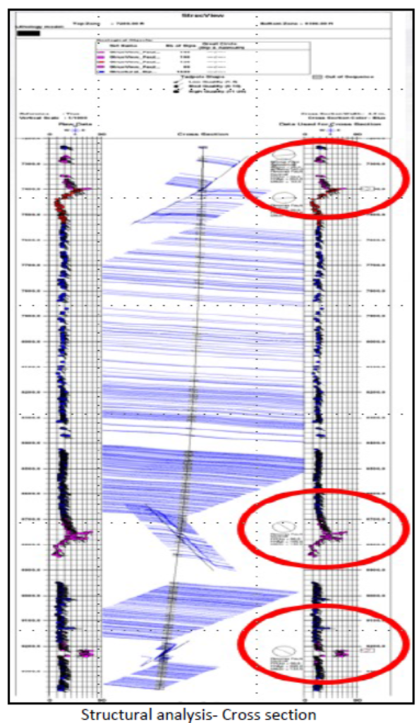
Structural interpretation is one of the main applications of borehole electrical image data. Such data is an important input into structural analysis such as interwells correlation, cross-section construction and mapping. Stereoplots and azimuth frequency diagrams are helpful in accurately determining the structural dip and used wherever possible.
For the purpose of structural geology interpretation dips in non-deformed shale are preferentially used to determine structural dip. Caution is required since shale can be deposited on a depositional slope and may have experienced non-tectonic post-depositional deformation including slumping, sliding, respectively beneath and above sand bodies, compaction and drape.
Structural interpretation includes defining structural dip zones, magnitudes and azimuths; identifying any angular unconformities; identifying and determining the orientation of features with a tectonic origin including unconformities, folds, faults and fractures.
In-Situ Stress Analysis
Imaging Services Applied to:
- FMS, FMI, FMI-HD (SLB)
- OBMI, Dual OBMI (SLB)
- UBI (SLB), Quanta Geo (SLB)
- CBIL, Earth Image (Baker)
- EMI, CAST, OMRI (Halliburton)
Deliverables:
- Image Stress Analysis Summary Report in Power point format including stereonets, Rose plot and hole shape information.
- 1:20 & 1:240 scale processed image & dip picking interpretation log prints (PDF).
- Dip sets for the Stress analysis data (Borehole Breakouts and Drilling Induced fractures) in LAS, XLS, XML
Benefits:
- Determination of regional minimum and maximum horizontal stress directions from Borehole Breakout and Drilling Induced Fractures.
- Hole ovalization from Hole Shape Analysis.
- Correlation with World Stress Map.
Turnaround time (TAT):
- Standard TAT is 2-5 days (determined by image log length & image quality).
- Rush TAT can be achieved <24hrs after acquisition.
The magnitude and orientation of stresses in the subsurface can affect borehole stability and other drilling or production properties. Borehole stress can cause rocks to fail in two modes, shear and tensile failure expressed as borehole breakout and drilling induced fractures. Stress analysis involves the analysis of stress related features identified on the borehole image, such as borehole breakout and drilling induced fractures. The orientation of these features is used to infer In-situ min and max horizontal stress directions in the vicinity of the borehole.
The analysis of drilling induced fractures and breakouts (considered here as stress-related indicators) provides not only the direction of the principal horizontal stress, but also calibration points for 1D and 3D mechanical earth models (MEM). In vertical wells the orientation of borehole elongation is aligned with the minimum horizontal stress. Similarly, the strike of drilling induced fractures is aligned with the maximum horizontal stress.

Fracture Analysis
Imaging Services Applied to:
- FMI, FMI-HD, ThruBit, MicroScope-HD (needs to be calibrated)
- OBMI, Dual OBMI, UBI, Quanta Geo fracture statistics only (fracture aperture/porosity not possible).
Deliverables:
- 1:20 & 1:240 scale processed image & fracture analysis log prints (PDF).
- Fracture analysis statistics (XML,XLS,LAS).
Benefits:
- Manual method of dip picking
- Fast, automatic method of fracture identification by segment extraction.
- Fracture statistics (count, density, length, area) for all imaging tools.
- Fracture aperture and porosity calculation for FMI images, providing indication of potential flow contribution.
- Input to discrete fracture network modelling and reservoir and completion quality evaluation.
Turnaround time (TAT):
- Standard TAT is 1-3 days (determined by image log length & image quality).
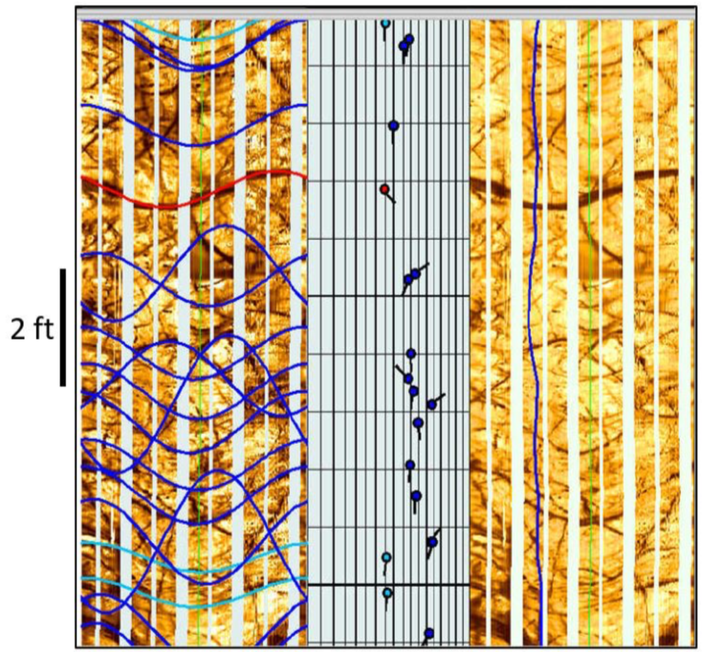
Natural occurring open fractures are very important to producibility in many carbonate and sandstone reservoirs. Fractures are planar features with no apparent displacement of blocks along their planes. Generally, they have a steep dip in tensional and wrench regimes. Whereas in compressional regimes, they may have high to low angle dips. Their aperture may be open, tight (closed) or filled with some minerals like clays, calcite, anhydrite, pyrite etc.
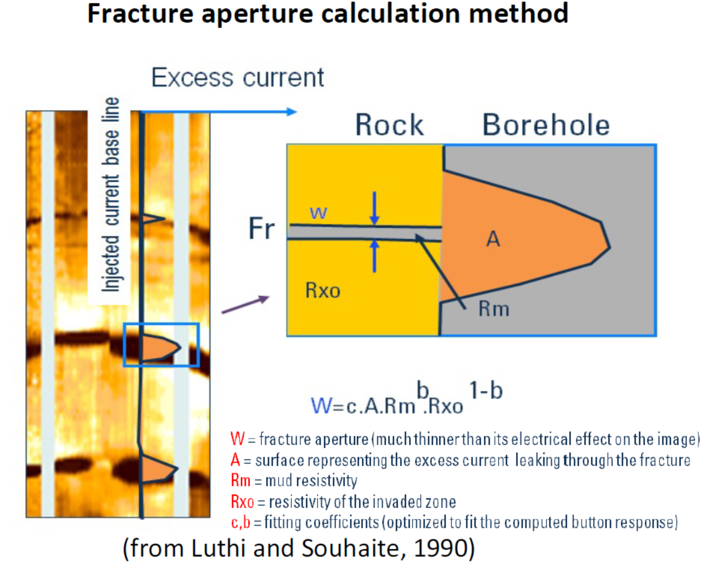
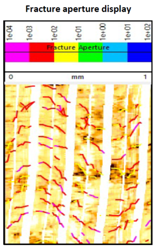
Fracture Analysis products include: fracture statistics, such as count, length and density, fracture morphology (fracture type); however, for an FMI image, it also uses the Luthi & Souhaite equation to compute fracture mean aperture, hydraulic aperture (providing an estimate of fracture flow potential) and porosity. Fracture porosity can be used in carbonate reservoirs for comparison with vuggy porosity, as part of overall secondary porosity calculations.
Fault Analysis
Imaging Services Applied to:
- FMS, FMI, FMI-HD (SLB)
- OBMI, Dual OBMI (SLB)
- UBI (SLB), Quanta Geo (SLB)
- CBIL, Earth Image (Baker)
- EMI, CAST, OMRI (Halliburton)
Deliverables:
- Image Fault Analysis Summary Report in Power point format including stereonets, and rose-plot information.
- 1:20 & 1:240 scale processed image & dip picking interpretation log prints (PDF).
- Dip sets for the Fault analysis data in XML, LAS/XLS format.
Benefits:
- Manual method of dip picking
- Input to discrete fracture network modelling and reservoir and completion quality evaluation.
Turnaround time (TAT):
- Standard TAT is 1-3 days (determined by image log length & image quality).
Structural breaks such as faults or unconformities are discernable from borehole electrical image data if there is an associated deformation (e.g., tilting, drag folding, etc.), which will be manifested as zones of dip rotation.
Sub seismic faults have features similar to fractures; the images on the two sides of the plane either have a different texture or aspect, or display a loss of continuity between the two sides of the event. Small depth shifts between similar features on each side of an oblique event can indicate a microfault
Although dip patterns computed from dipmeter are useful for fault detection, borehole images are the best way to accurately recognize faults. The analysis of dips through stereographic projection permits recognition of patterns related to faults. Image analysis provides accurate orientation of the fault plane and determination of its dip.

Sedimentary Analysis
Imaging Services Applied to:
- FMS, FMI, FMI-HD (SLB)
- OBMI, Dual OBMI (SLB)
- UBI (SLB), Quanta Geo (SLB)
- CBIL, Earth Image (Baker)
- EMI, CAST, OMRI (Halliburton)
Deliverables:
- Image Sedimentary Interpretation Report in power point format.
- Statistical analysis plots & rose diagrams.
- 1:20 & 1:240 scale processed image & dip picking interpretation log prints (PDF).
- Sedimentary facies, associations, Structural dip –removed Sedimentary Crossbed data (XML,XLS/LAS).
Benefits:
- Core to image calibration
- Generation of Depositional Model
- Paleocurrent and sand body determination.
- Key input to 3D facies model.
Turnaround time (TAT):
- Standard TAT is 5-7 days (determined by image log length & image quality).
Optimizing reservoir recovery requires reliable sedimentological models. Borehole electrical imagery, integrated with selective conventional core data, constitutes a very powerful and effective technique for use in detailed reservoir characterization and further field development.
Borehole images are used to identify sedimentary, biogenic and diagenetic structures as well as sand body orientations within a facies succession, which is of great value in interpreting depositional environments. Borehole images, when calibrated to core, can be useful for identifying image log criteria that can be used for interpreting image-based facies and facies associations.
It is important to highlight that borehole images provide paleocurrent determination, heterogeneity (textural) analysis and sand count analysis.

Facies Analysis
Imaging Services Applied to:
- FMS, FMI, FMI-HD (SLB)
- OBMI, Dual OBMI (SLB)
- UBI (SLB), Quanta Geo (SLB)
- CBIL, Earth Image (Baker)
- EMI, CAST, OMRI (Halliburton)
Deliverables:
- Image Facies Analysis Interpretation Report in power point format.
- 1:20 & 1:240 scale processed image & dip picking interpretation log prints (PDF).
- Sedimentary facies, associations, Structural dip –removed Sedimentary Cross bed data (XLS, LAS, XML).
Benefits:
- Image-based facies identification.
- Core to image calibration
- Generation of Depositional Model
- Paleocurrent and sand body determination.
- Key input to 3D facies model.
Turnaround time (TAT):
- Standard TAT is 5-7 days (determined by image log length & image quality).
Individual image-based facies can be defined based on detailed description of lithology and sedimentary structures from core data and calibrate to borehole image logs. Individual image-based facies are descriptive terms only and should not be taken alone as indicators of depositional environment.
Figure below shows an example of core-and image-derived facies scheme based on an image to core calibration (Gamero et al., 2011). During the facies analysis process all image-based facies are interpreted based on the transport mechanisms during deposition. The vertical stacking of image-based facies constitutes a facies association generated by the lateral migration of the depositional environment.
TECHLOG provides infinite flexibility for defining your own image-based facies schemes. You can tailor existing schemes to your own needs, or define entirely new ones; interactively point and click to define facies units. Display any supporting data with your facies display to enable you to quickly identify your units using facies as a discriminator e.g., cross plots, histograms, net pay computation, etc. Several different facies interpretations can also be performed in a well allowing geologists to compare different interpretations.

Matrix Computation
Imaging Services Applied to:
- FMS, FMI, FMI-HD, Inverted Quanta Geo (Matrix Computation)
Deliverables:
- Matrix conductivity image (DLIS & XML) and averaged conductivity channel (LAS, DLIS, XML)
Benefits:
- Removes non-cross features and computes matrix conductivity image which can be used for high resolution well correlation & sequence analysis and heterogeneity analysis.
Turnaround time (TAT):
- Standard TAT is 1 days.
Matrix computation
Matrix computation consists on the extraction of a background conductivity image or matrix image from a calibrated FMI image (or inverted Quanta Geo image) . The background of the image (i.e. matrix) is computed by removing non-crossing features on images such as vugs, molds, fracture segments, and intraformational conglomerates. The input image of Matrix Computation plugin is an electrical borehole image calibrated to conductivity or resistivity. An averaged matrix conductivity curve is also produced which can then be used for high resolution well correlation and sequence analysis.

Textural and Porosity Analysis in Carbonates
Imaging Services Applied to:
- FMI, FMI-HD
- Quanta Geo
- OBMI/Dual OBMI (limited use of PoroTex)
Deliverables:
- Image Porosity analysis Interpretation Report.
- Statistical analysis plots & rose diagrams.
- 1:20 & 1:240 scale processed image & dip picking interpretation log prints (PDF).
- Sedimentary facies, associations, pore space type outputs, secondary porosity (XLS, LAS, XML).
Benefits:
- Image-based facies identification.
- Core to image Calibration
- Generation of Depositional Model.
- Classification of different pore space types
- Generation of heterogeneity image summary curves
- Total image porosity computation and porosity spectrum
- Quantification of secondary (vuggy) porosity, types of pore space & flow potential
- Key input to 3D facies model.
Turnaround time (TAT):
- Standard TAT is 3-7 days (determined by image log length & image quality).
Sedimentary analysis involves the identification of image-based facies by inspection of the texture and fabric of the image, in conjunction with the dip picking results, petrophysical data, mud-log and conventional core (if available). These image-based facies are then used to infer facies associations indicative of specific depositional environments, and then used to generate an overall depositional model. Image-based facies can also be “calibrated” with core-based facies and extended into non-cored intervals. Facies data can be used as a key input for a 3D facies model.
Many carbonate rocks have complex dual porosity systems with varying proportions of primary & secondary porosity. Heterogeneity analysis can be used to classify the different types of pore space: vug to vug, isolated, connected to fractures, aligned at bed boundaries, or within rock matrix. The contribution of these different pore types to the total porosity of the formation is quantified in addition to the geometric information of delineated pore space. In addition, the porosity image, porosity spectrum and the connectedness of the different types of porosity can be quantified.

SELECTED REFERENCES
- Contreras, C. C., and H. Gamero, 2000, High-resolution borehole images as powerful reservoir characterization tools: Transactions of the GSTT 2000 SPE Conference, Port of Spain, Trinidad 10–13 July, 2000, http://www.gstt.org/
publications/transactions_of_ gstt_2000_spe.htm (accessed July 2010). - Contreras, C. , Gamero, H., Geel, C., Luthi, S., Hodgetts, D., Hu, Y., Johannessen, E., Johansson, M., Mizobe, A., Montaggioni, P., Pestman, P., Ray, S., Saltmarsh, R., Garnett, S., Hodgson, D., Leyrer, K. and B. Newberry, 2003, Investigating Clastic Reservoir Sedimentology. Oilfield Review. 15. 54.
- Etchecopar, A., Yamada, T. and P. Cheung, 2013, Borehole images for assessing present day stresses, Soc. Geol. France, t. 184, no 4, pp. 307 – 312.
- Gamero, H., Contreras, C., Pestman, P. and A. Mizobe. 2000. Borehole Electrical Images as a Reservoir Characterization Tool in the Merecure Formation, Guarico 13 Field, Eastern Venezuela. DOI:10.3997/2214-4609-pdb.118.
044eng - Gamero Diaz, H., Contreras C., Lewis, N., Welsh, R. and C. Zavala, 2011, Evidence of shelfal hyperpycnal deposition of Pliocene sandstones in the Oilbird Field, southeast coast, Trinidad: Impact on reservoir distribution, in R. M. Slatt and C. Zavala, eds., Sediment transfer from shelf to deep water – Revisiting the delivery system: AAPG Studies in Geology 61, p. 193-214.
- Gamero Diaz. H., Contreras Fuentes, C., Sturm, S. and J. Kherroubi, 2014, Applications of Borehole Images for Optimal Completion in Shale Plays, EAGE Borehole Geology Workshop, Oct 2014, cp-433-00014. DOI: https://doi.org/10.3997/2214-
4609.20142325 - Gamero Diaz, H., Mohsin, L., Desroches, J., Waters, G. A., Peralta J. D. and O. Al Zeidi, 2017, Importance of Borehole Images and Dipole Sonic Data for Optimal Stimulation in a Tectonic Compressive Setting, SPE-188474-MS, https://doi.org/10.2118/
188474-MS - Kourta, M., 2010, Combined Acoustic & Resistivity Borehole Imaging Review of Interpretation Results Well: E17a-A3 Gaz de France – Suez – Netherlands OBMI UBI Amplitude UBI: https://slideplayer.com/slide/
13378956/ - Luthi, S. M and P. Souhaite, 1990, Fracture apertures from electrical borehole scans. GEOPHYSICS 55: 821 – 833.
- Techlog https://www.software.slb.com/
products/techlog/techlog- geology/wellbore-imaging - Yamada, T., Quesada, D., Etchecopar, A., Le Nir, I., Delhomme, J., Russel-Houston, J., and Putra Perdana , T, 2013, Revisiting Porosity Analysis from Electrical Borehole Images: Integration of Advanced Textural and Porosity Analysis.
- Gamero Diaz, H.. , Mohsin, L.. , Desroches, J.. , Waters, G. A., Peralta, J. D., and O.. Al Zeidi. «Importance of Borehole Images and Dipole Sonic Data for Optimal Stimulation in a Tectonic Compressive Setting.» Paper presented at the Abu Dhabi International Petroleum Exhibition & Conference, Abu Dhabi, UAE, November 2017. doi: https://doi.org/10.2118/188474-MS
